|
HOME-MADE HOSPITALS FOR BUDGIES / PARAKEETSTHREE HOSPITALS FOR DIFFERENT ABILITIES
A BUDGIE HOSPITAL (BRICK-WOOD STYLE USING PAVING STONES) A dedicated budgie hospital on permanent standby can save a fortune in vet fees. The vast majority of birds who fall ill will die not from the initial complaint but from hypothermia. The bird will be too sick to feed and when the crop is depleted will lose heat rapidly. The hospital when correctly set can drastically reduce this heat loss thus giving precious time for the bird to recover. For best treatment, the bird must be placed immediately in an environment where the temperature is held at between 29 and 33 degrees centigrade. The hospitals described here provide this environment. ************************************************************************************
THE BRICK-WOOD HOSPITAL
************************************************************************************
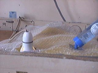
This is a relatively simple project with no thermostatic control - the temperature being set manually by a dimmer switch. Because of this, the unit must be kept in a room with fairly constant temperature (within 5 degrees centigrade) otherwise the dimmer will need to be periodically adjusted. This hospital is built on the same simple principles as the BRICK-WOOD NESTS. Bricks are laid out on a piece of chip board then the whole assembly is clamped together by the front and rear boards by means of 6mm threaded rods. A lid hinged to the back board serves as a roof. A single 75 Watt BLACK LIGHT (incandescent) mains bulb is fitted to the roof and serves as a heating element. This MUST be wired in series with a DIMMER controller to allow precise setting of the temperature. The bulb can be fitted using a skirt clamp. These come with lamp holders with H.O. skirts and should be glued to the top of the roof using wood glue. A thin stone slab placed directly below the lamp will act as a heat absorber and prevent the floor becoming too hot. Staple an aluminium sheet at least 4 inches (10cm) in diameter onto the ceiling directly above the bulb to protect the wood from the rising heat. An aluminium seal from a 1kg COFFEE-MATE tin is ideal for this as it is "dimpled" and fairly rigid. The dimmer, a junction box, a switch and a thermal cut-out thermostat are fitted to the back board by a qualified electrician. Cardboard shims are inserted between the bricks to prevent cracking on compressing the rods. Insulate the unit by placing expanded polystyrene (ceiling tiles or from a roll) below the base board. Do the same for the roof and left hand side and cover with thermal fleece. This improves the insulation and prevents pecking by the aviary birds. There are some issues regarding thermal fleece and I suggest covering this layer with bubble wrap (small bubbles). The better the insulation is, the more uniform the temperature will be and the less power will be consumed by the lamp. The hospital was originally constructed as a nest and strictly speaking the nursery room is not needed. However, this room will be at a lower temperature than the main room (vestibule) and will provide refuge should the main room become too warm. Cut-outs in the front board will act as inspection windows and will obviate the unavoidable heat loss when opening the roof. Use a small picture frame which may be fixed and fitting a sheet on this will improve the insulation and efficiency. This could possibly be another picture frame or a piece of plastic. The nursery window should be left "single glazed". Spot both in the usual way. Include the CHICKS GUARD BOARD as the unit may need to be used as a nest. The nozzle of a water bottle can be inserted through a hole in the roof to the left of the wooden block. A separate water provision is necessary for birds not familiar with these.
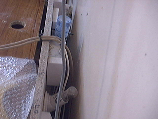
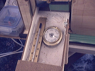
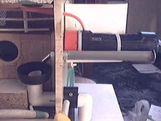
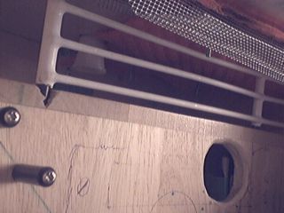
THE SAFETY CUT-OUT THERMOSTAT A capillary control thermostat is needed in case the dimmer fails and goes short circuit. These sensors operate without electronics and are intrinsically safe. They come with a fluid filled copper tube (THE SENSOR) which is connected to a switch by a thin tube. They are coiled up for dispatch and may need to be unwound for fitting. The prototype used a FANTINI COSMI IP40 from FARNELL ELECTRONICS. Fit the tube inside the unit to the top of the back board using plastic clips and leave the rest to the electrician. This thermostat operates as a "FAIL - SAFE" and must NOT be used to set the temperature. LEFT: THE SAFETY CUT-OUT THERMOSTAT TUBE FITTED TO THE BACK BOARD ABOVE THE DIGITAL TEMPERATURE PROBE. THE FOLLOWING THREE IMAGES ARE FROM THE NEW HOSPITAL BUILT ABOVE WHICH IS UNDER DEVELOPMENT BUT THE PRINCIPLES ARE IDENTICAL. RIGHT: A 60 WATT SPOT BULB USED AS A HEATER WITH ITS ASSOCIATED REFLECTOR. THE LARGER "COFFEE-MATE" REFLECTING DISK SHOULD BE USED IN THE CURRENT DESIGN.
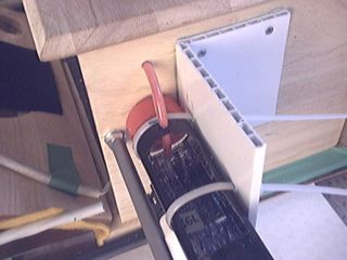
LEFT: B.C. LAMP SOCKET (UK) WITH H.O. SKIRT. The roof insulation consists of an expanded polystyrene sheet over which lies a layer of thermal fleece followed by a layer of bubble wrap (small bubbles) RIGHT: COMPONENTS ON BACK BOARD OF NEW HOSPITAL FROM TOP:
DIMMER SWITCH: JUNCTION BOX: WATER FEEDER: RELAY (NOT APPLICABLE): NIGHT TIME BALLAST BULB (NOT APPLICABLE): ON/OFF SWITCHES.
TEMPERATURE MEASUREMENT Accurate measurement of temperature is essential and I recommend a digital thermometer with attached probe. This can be inserted in a hole in the back wall after first placing in a protective tube. Arrange for the probe to extend into the room for about an inch (25mm). Alternatively a remote sensor from a wireless weather station can be taped onto the wooden block. Tape over the LED to prevent startling the bird. SETTING THE SAFETY CUT-OUT THERMOSTAT (To be conducted at an ambient temperature between 20 degrees and 25 degrees centigrade) 1. Set the safety cut-out thermostat to maximum temperature.
2. Adjust the dimmer to set the temperature of the unit to 35 degrees centigrade.
3. When the temperature has stabilized, slowly back off the safety cut-out control until the bulb switches off.
4. Note the cut out temperature over a few cycles to verify that this consistently lies between 33 - 35 degrees centigrade. If not, adjust the safety cut-out thermostat accordingly.
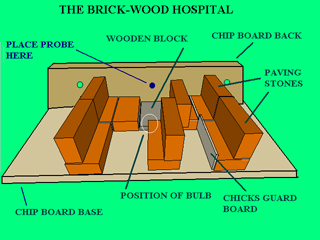
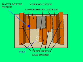
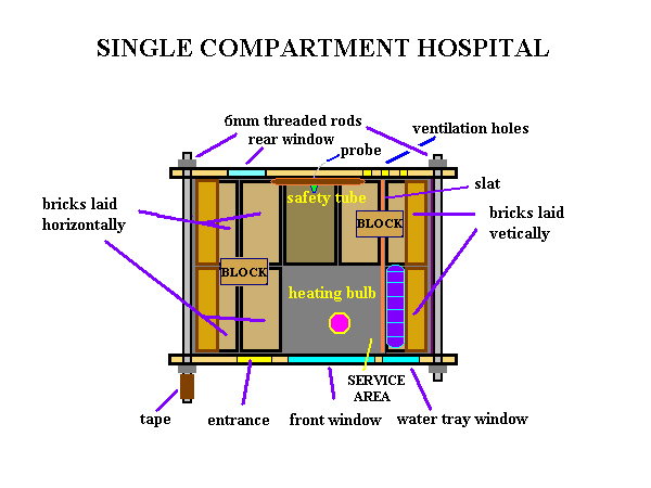
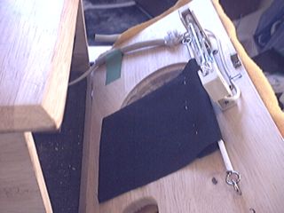
DIMENSIONS: The bricks are normal UK paving stones available from DIY stores. LENGTH = 20 CM WIDTH = 10 CM HEIGHT = 5 CM WOODEN BLOCK LENGTH = 20 CM WIDTH = 13 CM TOTAL LENGTH = 53 CM (EXTERIOR BRICK-BRICK) TOTAL WIDTH = 40 CM (INTERIOR) HEIGHT (INTERIOR) = 15 CM LEFT: THE ORIGINAL HOSPITAL AS DESCRIBED BUT NOW USED AS A RETREAT IN THE COMPOUND ..................
RIGHT: THE 60W SPOT BULB IN THE NEW HOSPITAL.
COMMISSIONING Once complete, check for sharp objects etc and plug the unit into a digital power meter. This will be needed to calibrate the hospital. Switch the unit on and set the dimmer to half way giving approximately 30 Watts to the bulb. Note the hospital temperature along with the ambient temperature and input power when it has stabilized after say 12 hours. Repeat for various ambient temperatures and input powers. With this data, the power required for a specific unit temperature can be found.
Once calibrated set the temperature to about 28 degrees centigrade and make daily records of it's fluctuations. At no time should the temperature exceed 33 degrees centigrade. Note that any adjustment to the dimmer may need up to 12 hours to fully take effect. USAGE (ROUGH GUIDE) PLACE A SEED TRAY WITH 50/50 BUDGIE SEED AND A MILLET SPRAY IN THE HOSPITAL BEFORE INTRODUCING THE BIRD. RUN DOWN LETHARGIC BIRD: 27 degrees C ILL BIRD - CAN'T FLY: 29 degrees C VERY ILL BIRD - CAN'T FLY - CAN'T STAND - MORIBUND: INITIALLY AT 32 degrees reducing gradually on improvement. HAND FEED WITH CREAMY MILK (3 PARTS POWDERED MILK, [FROM VEGETABLE OIL] - COFFEE MATE ETC, 1 PART POWDERED MILK [FROM COWS] - MARVEL ETC. SUPPLEMENT WITH VITAMINS. CONSULT AN AVIAN VET AS SOON AS POSSIBLE INSTRUCTIONS FOR THE ELECTRICIAN Fit a junction box, dimmer controller, capillary control thermostat and switch to the back board of the unit. Wire in series with the bulb socket as usual. THEORETICAL SPECIFICATIONS: 0.3 DEGREES CENTIGRADE ABOVE AMBIENT PER WATT. AMBIENT TEMPERATURE RANGE = 8 - 30 DEGREES CENTIGRADE FOR 30 DEGREES INTERNAL TEMPERATURE. MAX INTERNAL TEMPERATURE AT FREEZING POINT = 22 DEGREES CENTIGRADE.
-------------------------------------------------------------------------------------------------------- THIS HOSPITAL AND ITS WIRING IF PLACED IN THE AVIARY MUST BE MADE INACCESSIBLE TO THE BIRDS -------------------------------------------------------------------------------------------------------- THE BUDGIE HOSPITAL This is a single compartment version of the unit described and is simpler to build. Construction details can be found
HISTORY: This hospital in its basic form (single room) was used to treat two very sick hens. An albino hen became ill and after four days in the hospital at 30 degrees centigrade made a complete recovery. A young hen became seriously ill later on with what appeared to be a viral infection. After a prolonged period in the hospital although not completely recovered, she was well enough to cope by herself.
IMPROVEMENTS: The slat which retains the water tray can be extended to the ceiling and the right hand side of the hospital left un-insulated. This would create a cooler space for when the bird recovers and also act as an emergency retreat should the main room become too hot. Tonics can be administered via the water tray.
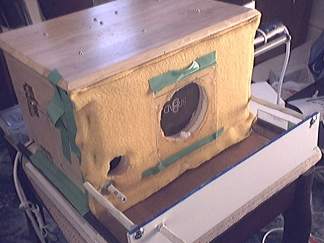
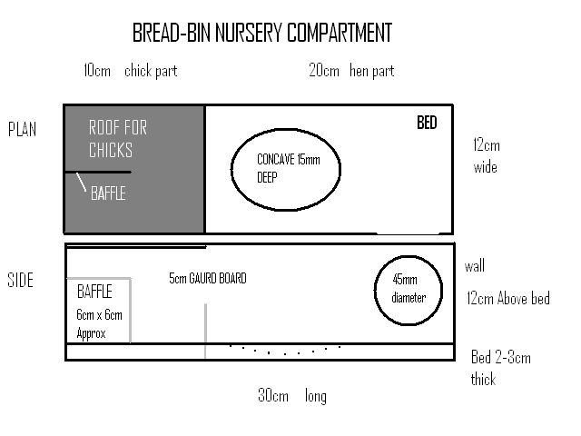
************************************************************************************ AUTOMATIC HOSPITAL EMPLOYING A THERMOSTAT ************************************************************************************ This is a sophisticated unit and once set at the correct temperature requires no further attention. It requires knowledge and experience in ELECTRONICS. The unit originaly was constructed as a nest but didn't function in this capacity. The NURSERY BOX should however be included as the birds used this compartment - because of the warm bed perhaps or the seclusion. They would also retreat into this compartment when providing feed etc. The heating is divided into two parts: 1. A 500W quartz halogen tube widely used for SECURITY FLOOD LIGHTING which is fitted on the lid of the BREAD-BIN. This tube is supplied with LOW VOLTAGE (23V - 24V from a 100VA low voltage transformer). ON NO ACCOUNT connect it to any MAINS supply. This would SET FIRE to the unit within a short time. 2. A series of 10W ceramic WW RESISTORS are fitted underneath the NURSERY compartment. These are operated at about 4.7 Volts. The combination of both these heating supplies results in an output of approximately 17 Watts and is sufficient to maintain the interior of the unit at 18 degrees centigrade above the ambient temperature. All surfaces except the left and right sides are insulated with pieces cut from expanded polystyrene ceiling tiles. The back and front are also covered with a layer of thermal fleece with the back having a further layer of hardboard. There are issues regarding thermal fleece and the front should be further covered with bubble wrap (small bubbles). The roof insulation lies under a false ceiling made from hardboard. A piece of aluminium foil is stuck to the ceiling directly above the tube to prevent scorching of the wood. I've used small blobs of BLU-TAK for this which creates insulating air pockets. This foil is a bit flimsy in use and a couple of overlapping disks from the COFFEE-MATE tins would probably be better. The floor insulation is fitted underneath the base. The front window is covered with a piece of plastic from a CD case giving a double glazed effect. These provisions enable the unit to run on permanent standby very efficiently. The average consumption with ten degrees above ambient is about ten Watts. The heating tube is arranged to be protected by a mesh grill when the lid is closed. This is simply a piece cut from a wire paper basket and stapled to the roof. Exposed sharp points on the mesh could be hazardous and I have glued along the exposed lengths of the mesh, PVC protectors. These are pieces of insulation from a cable cut along their lengths and slotted onto the mesh. The wires to the heater are protected by PLASTIC TUBING available from home brew shops. The bed which can be removed from the hatch at the side consists of a double wall socket pattress (UK) screwed onto a hardboard base. This is half filled with plaster and shaped to make a concave.
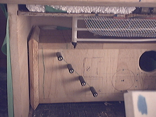
Cut a couple of 10cm holes at the base on each side to afford some ventilation. The fitting of a rubber mat in the bin improves the floor insulation and makes cleaning easier. This can be cut from an automobile foot-mat available from car accessory stores. This version of the hospital MUST be constructed and tested by a competent person with knowledge and experience in ELECTRONICS. THE UNDER-FLOOR HEATING 13 x 100 OHM CERAMIC 10W WW RESISTORS are fitted side by side on the under-side of the BISCUIT BOX. These are soldered on to PANEL PINS previously driven into the wood. The resistors are wired in parallel to give a total resistance of 7.7 OHMS. This resistor network is wired in series with the heating tube and gave a P.D. of 4.7 Volts across it which produced 2.9 WATTS
In the prototype, the heating tube and the resistor network were wired in series and and fed with 27.7 Volts A.C. Operation at 24 Volts should not make a substantial reduction in performance HEATER CONTROL SYSTEM The heating is THERMOSTATICALLY CONTROLLED by means of a VELLEMAN THERMOSTAT KIT (MK138) which operates at 12 volt stabilized D.C. The original biscuit box which was used for the nursery room was ideally suited to the fitting of the under-floor resistors. Should this box be no longer available, this part of the heating system can be dispensed with, with very little reduction in performance. The contribution from the nursery room is about 3 Watts and the contribution from the tube 14 Watts. A three position preset switch is used to give three set temperatures - 27 - 29 - 31 degrees centigrade. Owing to the high insulation and lack of a low temperature retreat I have omitted the 33 degree temperature setting. These settings are established by adding resistors in parallel with the thermistor sensor (NTC 10KO) of the Velleman kit in conjunction with the temperature control (RV1 100K)
POSITION 1 68K = 27 degrees POSITION 2 100K = 29 degrees POSITION 3 BLANK = 31 degrees
THE SAFETY CUT-OUT THERMOSTAT Fit the sensor bulb to the back wall at the top and the control to the base board. Wire in series with the heaters and the relay N.O. contacts. The connecting block can be shortened as four nodes have been used for a couple of test thermistors fitted in the nursery box. POWER SUPPLY: The unit is powered from a 230 Volt to 12-0-12 Volts 4 Amp (100 VA) mains transformer. The center tap is earth for the VELLEMAN THERMOSTAT. After passing through two 3.25 Amp 1.25 inch QB glass fuses, the secondaries are full-wave rectified by two 1N5408 diodes to produce around 17 Volts unregulated D.C. This is smoothed by two 470 uF 64 WV electrolytic condensers in parallel. A standard 7812 IC chip fitted with a small heat sink (10 degree centigrade per Watt) regulates this to produce a 12 Volt stabilized D.C. supply for the control thermostat. The heaters are wired after the fuses to the full 24 Volt secondary and is floating. The mains plug is fitted with a 1 Amp fuse. This supply is sufficient for three units. SETTING THE SAFETY CUT-OUT THERMOSTAT 1. Connect both heaters and the SAFETY CUT-OUT THERMOSTAT in series and connect to a 24V - 28V A.C. supply. 2. Set the safety cut-out thermostat to maximum temperature. 3. When the temperature reaches 33 degrees centigrade, slowly back off the safety cut-out thermostat control until the heaters switch off. 4. Note the cut out temperature over a few cycles to verify that this consistently lies between 33 - 35 degrees centigrade. If not, adjust the safety cut-out thermostat accordingly. 5. Connect the VELLEMAN thermostat in series for normal operation.
CALIBRATION: The unit should be calibrated at an ambient temperature between 20 degrees and 25 degrees centigrade. Place a digital thermometer on top of the NURSERY BOX and set the preset switch to POSITION 1. Set the thermostat control (RV1) to half way. Switch on and note the temperature every hour - take at least six readings. Leave overnight and note the final temperature in the morning. Make adjustments to the thermostat control (RV1) if the average temperature deviates from 27 degrees by 2 degrees or more.
THE BREAD-BIN HOSPITAL
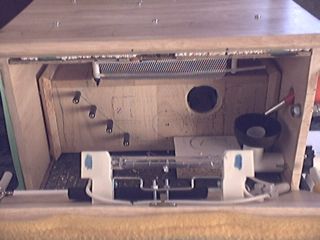
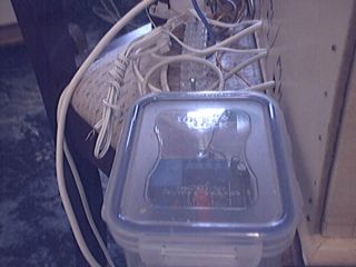
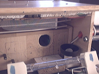
The resistor leads are taken out from the back and are connected to a junction box fitted to the base board. The thermostat PCB is housed in an air-tight sandwich box which not only affords protection against pecking but also against feather dust which in time could ingress into the control potentiometer. If the power supply and wiring are made inaccessible to the birds then the unit can be placed in the aviary without any further protection. THE INTERIOR SHOWING THE NURSERY COMPARTMENT AND THE THERMOSTAT IN THE LUNCH BOX AT THE REAR
FALSE CEILING WITH SPONGE MAT (RED) ............. HUMIDITY FEED TUBE (TOP RIGHT)
THE REMOVABLE BED IN THE NURSERY BOX
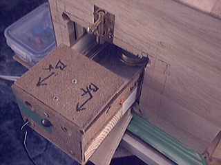
A 10mm hole can be cut in the end board to allow monitoring of the bird. .......................................................................................................... HUMIDITY CONTROL Low humidity levels were recorded which could lead to "stuck chicks" i.e. dead-in-shell chicks that have gone to term. Dry conditions which can lead to tough shell membranes have been suggested as a cause of this. The "red" tube leading from the water trough improves the humidity of the unit. The tube is fitted with sponge material which dips into the water trough and is in direct contact with a sponge mat stapled to the roof. Capillary action draws water to this mat and improves the humidity. This solution was only partially successful. Owing to the narrowness of the tube, deposits built up and blocked the flow of water. A wider tube should solve this problem. FRONT AND OBLIQUE VIEW OF THE WATER TROUGH
THE WATER FEEDER The water feeder is easily made from simple household goods. With the nursery compartment fitted, there simply is not enough space for a water tray. A normal feeder bottle can be fitted to the side but this particular solution was developed to also provide flowing water for the aviary birds. A lot of birds prefer flowing water to still water and will use the trough when the water switches on. The trough consists of a 150ml CLASSIC HAMSTER DRINKING BOTTLE with the ball bearings removed. File the end of the nozzle down a fraction or use a hack-saw and the balls will drop out easily. Stain the bottle with indelible ink to give the birds more confidence - when drinking. THE AUTOMATIC WATER SYSTEM The feed to the trough is connected to the water mains through a pressure reducer and a solenoid activated water switch. This was scrapped from a washing machine. It's effectively a 240 Volt automatic tap. It is plugged into a normal seven day electronic timer which is programmed to operate for 5 minutes five times a day. The tray comes from a coffee jar cap and has a 22mm hole drilled in the center. Into this is inserted a short length of 22mm overflow pipe and fixed with glue. Alternatively a plastic welder may be used. The top of the tube needs to be about 5mm below the surface of the cap. In use the nozzle of the feeder trough is arranged to deliver water very close or even over-hanging the drain to minimize plashes. A full treatment of the automatic water system is beyond the scope of this work. POSITION OF THE HEATING TUBE ON THE LID AND THE HUMIDITY MAT ON THE FALSE CEILING
PROBLEMS: Some scorching of the humidity mat occurred on test which was alleviated by re-positioning the mat away from the tube. The unit has proved reliable in use and has been used as a nest as well as a hospital although no chicks hatched. Some distortion of the lid occurred due to the wood drying out which prevented it from closing properly. This increased the ventilation but not enough to impair its performance. HISTORY: This version was used to treat five birds. A hen became "run down" and lethargic. She wasn't "fluffed up" but wasn't flying about which was contrary to her normal nature. I placed her in the hospital for a few days as a precaution and on release had completely recovered. The temperature in this case was set to 27 degrees centigrade. A cock suffered precisely the same symptoms and given the same treatment. After three days he was released and had made a complete recovery. This bird was a very low ranking bird with little self confidence. After release for some unknown reason his confidence in the flock increased markedly. The third bird had rapidly become lame and was found on the floor on his back trying to right himself by pulling on his wing. He was put immediately in the hospital and given vitamins by means of the trough. A week later he was released as he didn't appear to have an infection and he slowly regained the use of his legs, although he never flew again. Many primary feathers in one wing were missing or truncated and I assume he suffered from a type of FRENCH MOLT. Two further birds were introduced too late and didn't recover. SPECIFICATIONS (APPROXIMATE): 1 DEGREE CENTIGRADE ABOVE AMBIENT PER WATT. AMBIENT TEMPERATURE RANGE = 15 - 30 DEGREES CENTIGRADE FOR 30 DEGREES INTERNAL TEMPERATURE. MAX INTERNAL TEMPERATURE AT FREEZING POINT= 15 DEGREES CENTIGRADE. ......................................................................................................... THIS UNIT IS NO LONGER RECOMMENDED AS A NEST DUE TO ITS SMALL SIZE AND BECAUSE NO CHICKS HATCHED IN IT. HISTORY. The nest had been made available to the flock for five years and was positioned on top of a wardrobe next to the BRICK-WOOD nest in the bedroom aviary. This nest was of the type having two compartments. The overwhelming majority of hens chose this nest to raise their young and this is the preferred design. The unit however worked well as a HOSPITAL which may have contributed to its lack of popularity. One hen laid but no eggs hatched. The same hen laid in other nests but all eggs were clear.
************************************************************************************
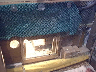
THE GROUND LEVEL HOSPITAL
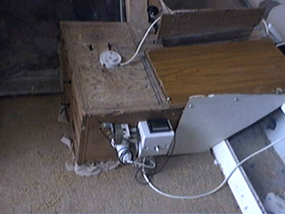
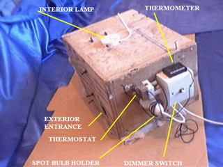
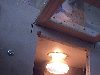
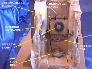
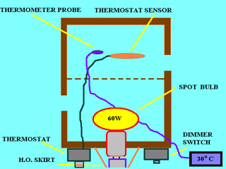
************************************************************************************ The condition of one bird deteriorated so slowly that by the time I realized what was happening it was too late. She was often seen tucked up on the floor near the small rooster and appeared to be okay otherwise. I took this to be a social problem but it probably was a slow acting virus. What was needed was a warm place at ground level where the birds themselves could walk into when needed. The box at the pyramidal walkway was ideal as it could then be used by all the birds in the aviary including those in the COMPOUND. The interior is divided into two parts using plastic gutter netting and entrance holes drilled on both sides. A fully enclosed wooden box with a hinged side would be suitable for just an aviary. All the interior surfaces apart from the end facing the glass are insulated with expanded polystyrene covered with a layer of cotton. The heating is provided by a simple 60 Watt spot lamp blackened with a felt-tipped pen and is fitted to the end of the box. The mains power input is controlled by a dimmer switch and thermostat which are also fitted to the end of the box. The wiring must be protected if cockatiels are present. The thermostat is of the hydraulic expansion type (pipe and tube) which are very reliable and don't need a power supply. The tube is fixed to the ceiling of the box and away from the lamp. The hysteresis is quite high with these types of thermostats (about 10 degrees C) but hasn't as yet proved to be a problem. It is adjusted to give a temperature range from 25 to 35 degrees C. The dimmer switch is rated at 150 Watts maximum. Higher power dimmers are not suitable. The temperature can be verified by a probe thermometer fitted to the side of the box. The probe itself is tie-wrapped to the ceiling of the box next to the thermostat tube and next to the interior lamp. The lamp-holder skirt and wood are first sandpapered then glued together with wood glue.
INTERNAL DIMENTIONS AT CEILING: 34CM LONG: 14CM WIDE: 13CM HIGH MEASUREMENTS ARE WITH 2.5CM THICK EXPANDED POLYSTYRENE INSULATION 2cm of insulation should suffice for a stand alone unit.
COMMISIONING: 1.Set the thermostat at its maximum setting. 2.Using a digital power meter adjust the dimmer to give an input power of around 20 Watts. 3.When the temperature reaches 35 degrees centigrade slowly reduce the thermostat setting until the lamp switches off. The internal temperature should then cycle between around 25 to 35 degrees centigrade. The calibration is best done between 15 and 20 degrees ambient temperature. The cycling time should then take between 5 and 10 minutes. Make adjustments to the thermostat if necessary and check each day for a week before making the hospital available to the birds. Place half a sprig of millet inside.
TO BE CONSTRUCTED BY PERSONS WITH KNOWLEDGE AND EXPERIENCE IN ELECTRICS
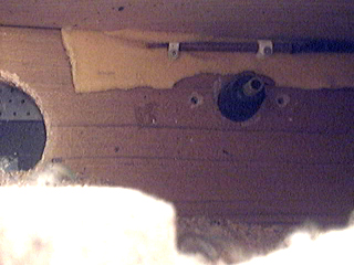
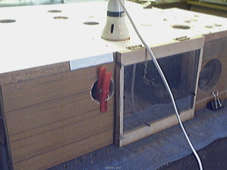
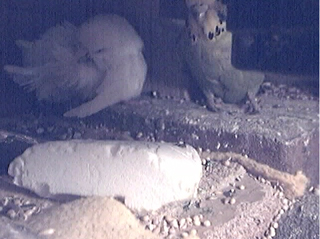
HOSPITAL IN PLACE AT THE COMPOUND ............... COMPOUND ENTRANCE
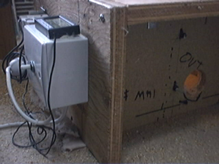
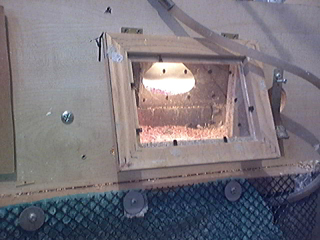
FRONT AND INTERIOR VIEW OF THE HOSPITAL
PLAN OF THE HOSPITAL (DIAGRAMMATIC)
HISTORY: As far as I'm aware only one bird has ever voluntarily used this hospital. An old and frail cock whose health had been slowly deteriorating had died in it. There were no signs of illness or injury and he was presumed to have died from aged related causes. His decision to enter the hospital suggests that he was aware of the warmth or that he wanted to spend his last hours in peace and safety which in itself is as valuable as leaving fully recovered.
|