AUTOMATIC LIGHTING SYSTEMS
An Automatic Lighting system gives a guaranteed period of light during the day to enable the birds to feed properly and to carry out their other duties in safety. Living in the temperate zone of the planet is an alien environment for exotic birds whose natural habitat is the tropical or subtropical regions. These regions have a minimum daylight period of 9 hours all through the year with temperatures rarely dipping to freezing point. In Scotland for example the average length of day in mid December is 7 hours - with 17 hours darkness with temperatures regularly plummeting below freezing. Some birds' crops can't hold enough food for that length of time and will not survive. Supplementary lighting is needed during these periods in an outdoor aviary and in all seasons in an indoor aviary. A minimum of two 60 Watt incandescent lamps are needed in case one blows and are set to operate from around 8:00 hours to 20:00 hours. These lamps don't have to be on all the time; however the first couple of hours in the morning and the darkness hours in the afternoon and evening should be covered. Operating the lamps manually can be very restrictive to ones’ life and an automatic system is preferred. Commercial systems are available but a home constructed unit can easily be built for those with technical knowledge. Three fully automatic systems are described - two with a warning buzzer and automatic dimming as used in the indoor aviaries and a simpler system using readily available domestic appliances and timers.
WARNING!
These are ENGINEERING projects which operate with LETHAL mains voltages and requires experience and knowledge in ELECTRONICS and high voltage kits.
AUTOMATIC DIMMING WITH WARNING BUZZ
These versions operate the lamps which dim off slowly at roosting time. A buzzer which intensifies in stages gives the birds ample warning to enable them to prepare for the night.
OVERVIEW:
A MASTER TIMER which sets the on/off periods of the room lamps feeds an AUTO-DIM CIRCUIT which in turn feeds a DC CONTROLLED DIMMER which dims the lamps.
THE MASTER TIMER:
The master timer is a motorised clockwork timer synchronised to the a.c. mains. This timer was a discarded "day/night" switch which was used in a domestic consumer unit to switch on night storage heaters. These are now obsolete but for this application were ideal. The advantage with these types of timer is that they don't need to be periodically adjusted as is the case with digital timers. Some of these however drift very slowly but it's the luck of the draw. The down side with motorised timers which includes segment timers is that they will need to be reset every time the power fails. Two on/off settings are provided which can be adjusted by the fingers as with a clock. A pair of electrical contacts open and close at these times which are used to control the auto-dimmer. These contacts are at mains potential and need to be isolated to operate the DC CONTROLLED DIMMER which is at low voltage. A 24 hour segment timer in conjunction with a mains relay can be used instead.
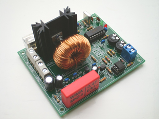
THE DC CONTROLLED DIMMER:
THE "DC CONTROLLED DIMMER" from Velleman is a circuit which is available in ready-built and kit form. This prototype used the original board which has been modified but the functionality is the same: The room lamps are connected to the output of the dimmer (Load) and a control voltage (0 - 12 Volts DC) is applied to the analog input. With zero volts applied to the input, the power to the lamps is zero, with 12 Volts applied, the lamps are supplied with full power. With a gradually falling input voltage, the lamps will dim gradually. This is what the AUTO-DIM CIRCUIT provides.
THE AUTO-DIM CIRCUIT:
This circuit provides around 14 Volts (depending on the vagaries of the mains supply) rectified and smoothed D.C. voltage (DCS) to the analog input of the DC CONTROLLED DIMMER. This maintains the lamps at full power. When the master contacts in the timer open this supply is cut off. However the lamps don't go out immediately but slowly due to the energy stored in a large capacitor which is also connected to the input of the DC CONTROLLED DIMMER.
THE BUZZER: This is a small electronic type buzzer which operates at 6 Volts.
THE AUTO-DIM CONTROLLER:
This unit contains the AUTO-DIM CIRCUIT and the DC CONTROLLED DIMMER
THE ORIGINAL CIRCUIT
(ADC MK1)
(This version is given for information only.)
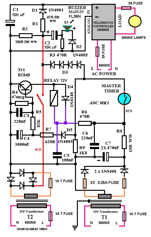
OPERATION:
T1 is connected permanently to the mains supply whereas T2 is connected to a 24 hour mains segment timer which operates around twenty minutes before the room lights dims. This also operates relays to dim the COMPOUND lamps (not described). Ignore T2 for the moment. The MASTER TIMER is ON supplying the DC CONTROLLED DIMMER with around 14 Volts DCS which maintains the room lamps at full power (Through D3, R1 and D1). C1 is also fully charged. C2 (which operates the buzzer) has charged through R3 but is prevented from reverse biasing the buzzer by D2. When the MASTER TIMER cuts out the potential at C2+ drops to a low value (depending on R2). This allows C2 to discharge (Through R2, R3 and D2/S1). This activates the buzzer for a few seconds. At the same time C1 is slowly discharging through the input of the DC CONTROLLED DIMMER. Now when T2 switches on before this the positive half cycles of the rectified a.c. (DCR) exceed the voltage from T1 by a few volts and charge C2 to this value. During the dips in the cycle the potential at C2+ drops back to the lower value allowing C2 to dump some charge through the buzzer by the same path. This causes the buzzer to sound feebly. The relay contact is closed due to TR1 conducting (Through R8 and R6). The base current is supplied through R8, the MASTER TIMER, D5, R7 and R5. When the MASTER TIMER cuts out, the relay contacts remain closed due to base current being supplied by C4. This has enough charge to hold it closed for about nine minutes. During this time the buzzer is louder as the potential at C2+ dips to a much lower value on each half cycle. When the relay finally drops out, the buzzer sounds even louder as it receives the full un-interrupted charge of C2. The sound dies away exponentially as the capacitor discharges.
ACTUAL PARTS USED:
T1 is a 12-0-12 Volt 4 Amp 100 Watt frame transformer. This transformer also supplied power to two nest heaters (500 Watt linear halogen tubes) drawing over an Amp.
D3 consists of 2 X 1N4003 in series with a 1N4148 and a BZTO3C10 zener diode in the forward direction.
R5 consists of 3 X 2M2 resistors and a 100K resistor all in parallel.
R8 consists of 1 X 4R7 resistor 7 Watt ww in series with a 10R resistor 10 Watt ww (On separate control panel).
T2 is no longer available but was probably a small plug in transformer of about 300mA rating and about 12 Volts output. It had an integral bridge rectifier with no smoothing condensers. This is important for the correct operation of the buzzer.
The relay is a BT type 47 (MAPLIN N17AW).
The buzzer S1 is a MAPLIN FL39N 6 Volt sounder.
All resistors are metal film 0.6 Watt unless otherwise stated.
All non electrolytic capacitors are metalised ceramic plate 63 Volt DC.
The circuit was assembled in a small plastic box on an 12 way 15A terminal block and a MAPLIN AD101 PLUGBLOCK (Breadboard). The DC CONTROLLED DIMMER was fitted to the base. The power supply was built separately.
HISTORY:
A single unit was built (see images) and employed in two separate aviaries over a period of six years during which it developed a single fault.
The triac Tr1 (DC CONTROLLED DIMMER) failed after the unit was installed in the new aviary and after replacement caused no further problems
ADC MKI
(Velleman DC CONTROLLED DIMMER on base - Old board)
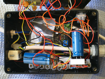
CABLES:
TOP LEFT - LOAD (Lamps - from Velleman board)
BOTTOM RIGHT - Mains power in to Velleman board.
BELOW THIS (Not visible) - MASTER TIMER (DCS) + D.C. Volts to TR1.
TOP RIGHT - Monitor cable with connecting block (Back-up lighting - Not described)
ABOVE THIS - D.C. Socket (For DCR)
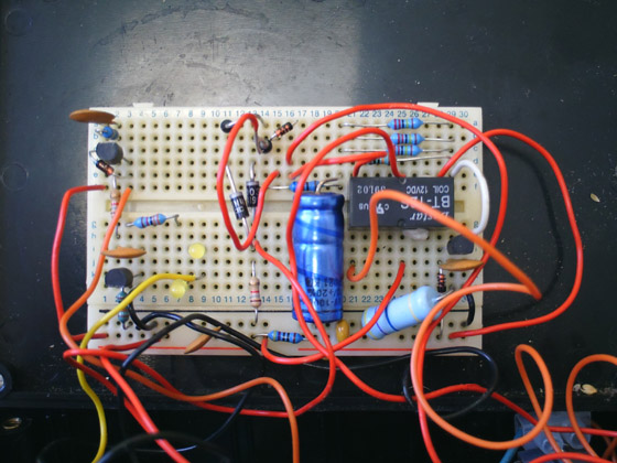
TR1, RELAY AND BASE COMPONENTS
(On lid)
The circuit on the left (Two transistors, L.E.D.s etc. belong to the Back-up lighting.)
IMPROVEMENTS:
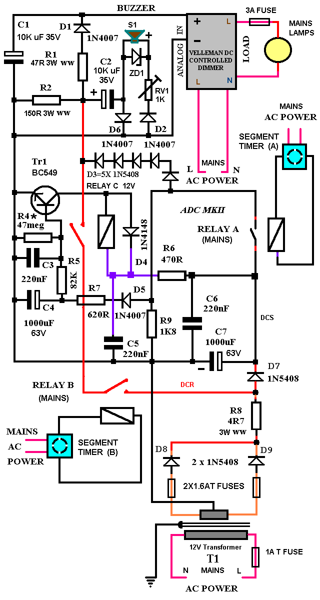
The feeble sound at stage 2 of the “countdown” sequence was subject to large variations to the point of being almost imperceptible at times. This was caused by the DCS voltage increasing due to the nest heating switching off together with supply variations. An improved circuit is given below. This circuit has the same functionality as the original but uses one transformer and mains relays apply the DCS and DCR voltages. Changing the number of diodes in D3 changes the volume of the buzzer when both sources are applied and an adjusting pot RV1 has been included to set an overall volume for all phases.
.
MODIFIED CIRCUIT USING A SINGLE TRANSFORMER
ADC MKII CIRCUIT DIAGRAM
CONSTRUCTION:
No issues were evident regarding the connecting block style of construction for the AUTO-DIM CIRCUIT but the small box made access to the Velleman board difficult. It was also necessary to cover the high voltage components with insulating tape due to their close proximity to the low voltage wiring. Fitting the components in a larger case and including the mains transformer should overcome these issues and simplify construction. A metal case will need to be earthed. If using the PLUGBLOCK, the relay needs to be stuck down as the pins are short and it will fall out after a while due to vibration from the buzzer. The unit doesn't generate much heat and a closely sealed box can be used as in the prototype. However at ambient temperatures over 30 degrees Centigrade or if the transformer is included a few ventilation holes should be provided. The volume control should be an internal preset.
TESTING:
D.C. CONTROLLED DIMMER.
After assembly check the wiring for shorts and mistakes.
Test and adjust the Velleman board on a regulated and adjustable 12 Volt D.C. supply. A 100 Watt or two 60 Watt incandescent bulbs can be used for testing. Follow the procedure given in the Velleman Illustrated assembly manual setting the maximum level to 12 Volts (RV2) and the minimum level to zero (RV1). Reduce the voltage slowly and check that the lamp dims off smoothly. For the pre-assembled unit test between zero Volts and 10 Volts. This range is not adjustable.
AUTO-DIM CIRCUIT TEST.
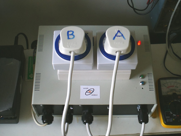
Two 24 hour SEGMENT TIMERS connected to the two mains relays (A and B) are used to switch the DCS and DCR voltages in and out of circuit. All segments of the timers are deselected and the side switches are used to operate the relays. Make sure both timers are switched off then plug them in.
Allow a couple of minutes between steps for the capacitors to charge.
1) Plug in T1 and note the voltage across C7. Readings should be around 19 Volts D.C. (19.3) [18.97]
2) Note the Voltage across C1. This should be zero.
3) Switch on RELAY A (DCS) and note the Voltage across C1 this should be about 12 Volts.
(13.96) [11.44] If less re-adjust the maximum level (RV2) on the D.C. CONTROLLED DIMMER.
4) Switch on RELAY B (DCR) and note the Voltage across C1. This should be about 15 Volts. (16.6 )(3V on buzz). [15.42] A humming sound from the buzzer should be heard.†
5) Switch off RELAY A and the buzzer will sound somewhat louder with a harsher tone. (10.4V BUZ)
6) Switch off RELAY B and the buzzer will sound even louder and die away in a few seconds.
CONNECT THE D.C. CONTROLLED DIMMER.
REPEAT THE ABOVE SEQUENCE (Without taking readings):
At 1) The lamp should be off.
At 3) The lamp should be on full.
At 4) The lamp should be on full.
At 5) The lamp should be on full.
At 6) The lamp should be on full dimming off slowly after about 40 seconds. The lamp should be completely off 45 seconds later.
REPEAT THE ABOVE SEQUENCE:
At 6) Leave the DCR relay switched on (RELAY B). RELAY C will cut out automatically after around 8 minutes followed by the lamp dimming off.
The volume at step (4) can be altered by altering the number of diodes in D3 - the more there are the louder the buzzer. This can also affect the brightness of the lamp but this can be compensated for by adjusting RV2 on the Velleman board. (Kit version only).
.
MK RELAYS are used for testing but hermetically sealed types are preferred due to possible problems arising from the ingress of feather dust.
† There are no issues regarding the over-voltage as this is well below the maximum ratings of the input circuit.
Readings in round brackets = taken from a simulator.
Readings in square brackets = actual measurements.
Readings taken with 243V a.c.mains.
ADC MKII
PARTS: MAPLIN CODE
C1, C2 10,000mF 35V (Not stocked)‡ N97KF (4700mF 35V X4)
C3, C5, C6 220nF 100V RA50E
C4, C7 1000mF 63V DT71N
D1, D2, D5, D6 1N4007 N78CA
D3, D7, D8, D9 1N5408 QL87U
D4 1N4148 QL80B
R1 47R 3Watt (wire wound) W47R
R2 150R 3Watt (wire wound) W150R
R4* 10Meg 0.6 Watt (47meg not stocked) M10M
R5 82K 0.6Watt M82K
R6 470R 0.6Watt M470R
R7 620R 0.6Watt M620R
R8 4R7 3Watt (wire wound) W4R7
R9 1K8 0.6Watt M1K8
RV1 1K Preset potentiometer UH00A
ZD1 BZV85C - 8.2V N45BZ
TR1 BC549C QQ15R
S1 Miniature Buzzer FL39N
RELAYS A/B MAINS DPDT N13AW (230V~ )
RELAYS A/B SOCKET (PCB) JG52G
SOCKET (CHASSIS) N36AW
RELAY C 12V Type 47 N17 AW
T1 Transformer 12-0-12 24VA N64JB (230/240V~)
PLUG BLOCK AD-101 AG09K
INLINE PLUG For DCR (2.5mm) HH62S
CHASSIS SOCKET For DCR (2.5mm) JK10L
FUSES 1.25AT 20mm (X2) GL60Q
FUSE HOLDERS 20mm (X2) KC01B
TERMINAL BLOCK 12 way 15Amp L98AR
D3, D7, D8, D9 1N5408 (Farnell Components) Order Code: 1467460
‡ C1, C2 10,000mF 40V (RS Components Ltd) Order Code: 208-7223
_____________________________________________________________________
VELLEMAN KIT D.C. controlled dimmer Velleman code K8064
PRE-ASSEMBLED D.C. controlled dimmer Velleman code VM165
CAUTION: Do NOT connect mains voltages to the PLUG-BLOCK!!
INSTALLATION: Fit the unit in a location which is not frequented by the birds such as behind a wardrobe or on the ceiling.
OPERATION:
MORNING
No countdown sequence is needed for the morning phase.
Set timer A to operate from 08:00h to 10:30h
EVENING
Set timer A to operate from 15:00h to 19:30h
Set timer B to operate from 19:15h to 19:45h
COMMISSIONING:
Your birds will be used to your normal “lights out” call and may be startled the first few times it is used and will not appreciate its purpose. Give your normal call after the final buzz for two or three nights then let the auto-dimmer take over. Sit with the birds for the first week to assess any problems. If after this period the buzzer still makes them jump or freeze then back off the volume - budgies have extremely sensitive hearing.
ADC MKII TEST BED
SAFETY NOTES:
Always disconnect the DC Controlled dimmer from the mains supply before wiring the socket or changing the bulb. The load terminals are still live in the early versions of the board even with the analog input terminals disconnected. This is due to the triac TR1 being wired in the neutral line. The current version has rectified this issue but still adhere to this advice as electronic switches don’t have the same degree of isolation and reliability as physical switches.
HISTORY:
This version is currently undergoing tests cycling twice a day using the early board and original components..
TEST RESULTS:
25/12/12 START
DATE FAULTS
08/02/13 NIL
09/02/13
Tested buzzer of recent manufacture - OK: Soldered leads onto zener diode as they are very thin and weren‘t being properly gripped by the connecting block screw.
VELLEMAN
D.C. CONTROLLED DIMMER self build kit
(K8064)
ADC-MKII (With new board and components) assembled and on test.
VELLEMAN D.C. controlled dimmer - KIT K8064 (U.K.)
VELLEMAN D.C. controlled dimmer - PRE-ASSEMBLED VM165 (U.K.)
***********************************************************************************
ALTERNATIVE SYSTEM
(For non breeding regimes without a compound)
This system uses three lamps which switch off in sequence to alert the birds to the forthcoming darkness.
PARTS REQUIRED:
2 X 50 Watt down lights (or spotlights).
1 X Bedside lamp (60 Watt).
3 X Digital plug-in timers.
Fit the down-lights on adjacent walls near the ceiling with one beaming towards the floor and the other towards the central feeding place. The bedside lamp can be placed in any convenient spot avoiding obvious problem areas such as near water trays or below roosting positions.
Plug the lamps into the timers on an extension cable and program them as follows.
MORNING
..................................................................................... ON ................... OFF
TIMER 2 (FEEDING PLACE DOWN-LIGHT) ....... 08:00 .................10:30
TIMER 3 (FLOOR BEAMING DOWN-LIGHT) ..... 09:00 .................10:25
EVENING
...................................................................................... ON ................... OFF
TIMER 1 (BEDSIDE LAMP) ...…………….............. 17:00 .................19:45
TIMER 2 (FEEDING PLACE DOWN-LIGHT) ….... 15:00 .................20:00
TIMER 3 (FLOOR BEAMING DOWN-LIGHT) ...... 16:00 .................19:55
The night lights should give sufficient light to enable a late feeding bird to get to its roosting spot. With this arrangement in place, the room light can be turned off at any time. Commission the system in summer or autumn to let the birds get used to it before it's really needed.
This simple "count-down" system should provide the birds with enough information to prepare for the night. Once the pattern has been adopted avoid making frequent and unnecessary changes as this will only confuse the birds.
POWER CABLES IN AVIARIES:
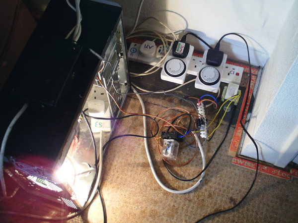
A power supply in an outdoor aviary needs to be installed by a registered electrician (U.K. regulations) or if self installed will need to be inspected. This person should be able to advise on ways to protect the cable from pecking from some breeds of birds and possibly vermin. P.V.C. CONDUIT/TRUNKING can be utilised in an indoor aviary. Budgies in my experience can differentiate between a power carrying cable and a similar cable provided as a perch and have never been known to unwittingly cause damage to a live cable. Deliberate sabotage of a low voltage lighting cable in a nest has been known - the hen may have been worried that her chicks could be seen. A single cockatiel had been known to peck at a mains power cable (From the auto-dim controller) and even in this case I believe it was a purposeful act. I therefore recommend that all exposed power cables in an aviary be protected.
Lamp dimming in the Attic aviary